Page 3 of 6
Re: Drive Well Project
Posted: Thu Dec 16, 2010 8:48 pm
by CC TX
Hi Pete.
Yes, the details for the front and rear drive supports is missing. I knew about it, just never got around to completing it. This is one part of the design that I never completely determined and just did some fitting to make it fit right.

This can be made out of 5/8" thick plywood or 4 layers of 4 mm plywood. The dimensions shown should be good for the rear support. The length of the front support may need to be adjusted. I will try to verify this tomorrow.
Re: Drive Well Project
Posted: Thu Dec 16, 2010 8:58 pm
by CC TX
Your plan of attack all sounds good.

PiratePete wrote:I am also thinking it it will be hard to glass the inside of the drive & only coat it in epoxy & glass the outside. ??
I totally agree. Even the outside is diificult with all of the corners. At least the outside will be hidden.
Re: Drive Well Project
Posted: Fri Dec 17, 2010 12:33 am
by PiratePete
Well I have the jig made up, all the pieces cut, ready to start to glue things together.
So I stitched the front deck into place & set the seat frame & front panel in place so I could check where every thing fits.
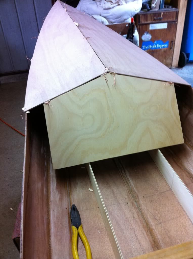
I sat the jig with the "Hobie Well" pieces taped to it in position & it looks good
The clamped on piece is where I am thinking of raising the cockpit floor back up & using the drive well as the front scupper.
I can glue it to the rear of frame 2 & to the sides of the seat frame. I might even be able to put a screw into the wings where the drive will be held down. With that & the base frame that is glued right round the bottom of the hull I would think I should have enough strength.
Re: Drive Well Project
Posted: Fri Dec 17, 2010 1:18 am
by CC TX
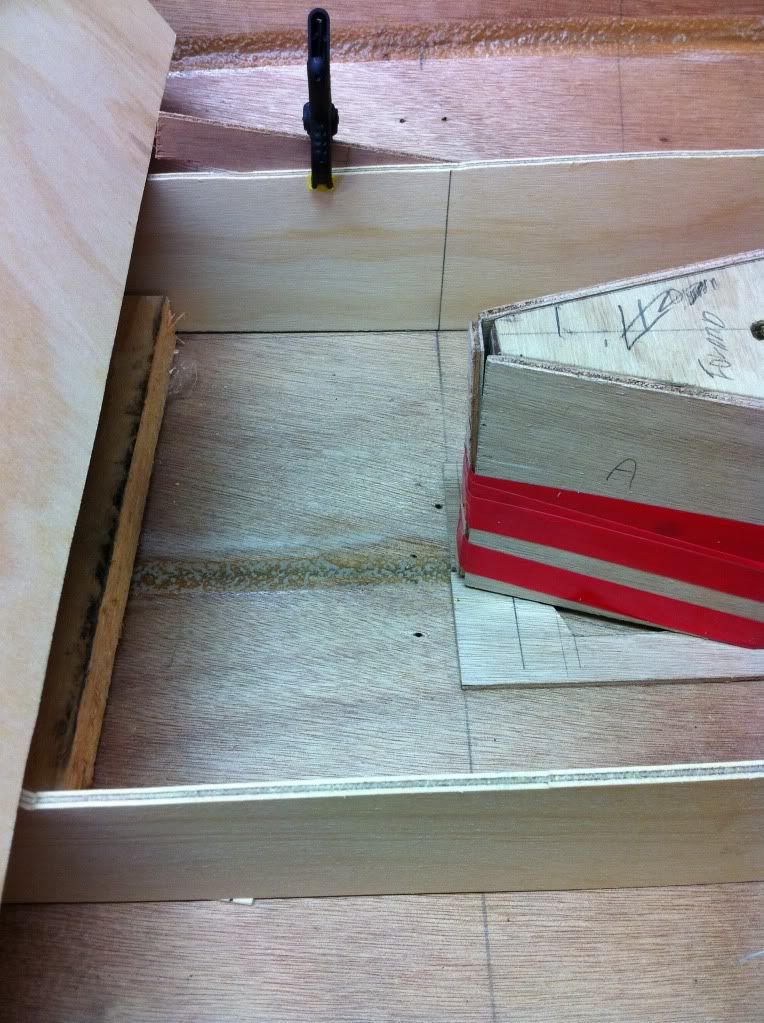
I'm not sure if I am looking at your pictures right. Part A should go toward the aft. Part B should go toward the forward end.
As a suggestiion, when you are gluing the pieces together on the assembly fixture, be sure to leave one of the A-C joints unglued; and, at the opposite corner, leave the B-C joint unglued. Otherwise, it may be difficult to remove the assembly fixture from the drive well.
Also, put tape or something on the assembly fixture under any joints that will be glued to prevent any epoxy sticking the parts to the assembly fixture.
Re: Drive Well Project
Posted: Fri Dec 17, 2010 1:55 am
by PiratePete
Re: Drive Well Project
Posted: Fri Dec 17, 2010 7:21 am
by CC TX
Sorry that I didn't provide any assembly instructions. I was thinking that I would be able to provide them as you build.
Re: Drive Well Project
Posted: Fri Dec 17, 2010 5:53 pm
by CC TX
CC TX wrote:Hi Pete.
Yes, the details for the front and rear drive supports is missing. I knew about it, just never got around to completing it. This is one part of the design that I never completely determined and just did some fitting to make it fit right.
This can be made out of 5/8" thick plywood or 4 layers of 4 mm plywood. The dimensions shown should be good for the rear support. The length of the front support may need to be adjusted. I will try to verify this tomorrow.
The dimesions are good. The front support will need to be shimmed to take the force of both legs pushing against the pedals; and, prevent the cradles (Part E) under cam lock knobs from being over stressed. More info on the shimming later. You can make the front and rear drive supports now; but don't glue them in place yet.
Can you provide more pictures of what you now have. I couldn't see what Part E, E2 look like. I need to know about where I need to start with the next instructions. My drawings aren't completely clear; since, there are many ways of doing this.
Re: Drive Well Project
Posted: Fri Dec 17, 2010 8:00 pm
by PiratePete
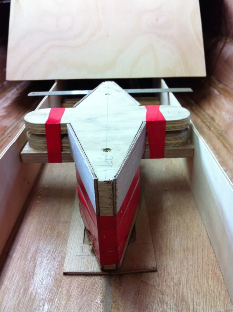
You were right about the well . . . . . it cracked as I puled it off to see how the drive fitted and it look like I am on the right track.
I have put it back on the jig & left 2 sides unglued so it will come off.
I only glued the E & E2 parts together this morning & cant get a picture of it for you. I have been wracking my brain on how I can set it up to machine the recesses in them. I have pretty well worked out how to do the hod down clamps. I have a sheet of aluminium that I am going to make my rudder blades out of & intend to make a washer out of it & have some ply with the groove in it & use a 10mm s/steel bolt & wing nut. I will put a tie wire through the top of the bolt so the nut wont come off.
I will see if I can do a drawing for you.
Re: Drive Well Project
Posted: Fri Dec 17, 2010 8:01 pm
by PiratePete
What time zone are you in.
Tasmania, Australia is on UTC + 10 & at the moment we are in day light savings so its UTC + 11
Re: Drive Well Project
Posted: Fri Dec 17, 2010 8:42 pm
by PiratePete
Here is what I was thinking of
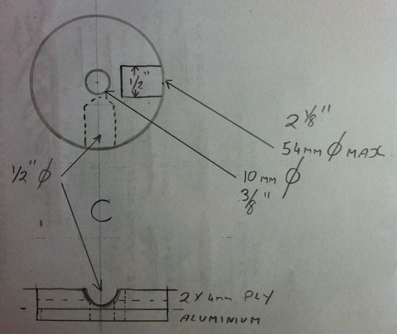
I think it will end up about 50mm or 2" in diameter.
I also might make the cut outs at 120 degrees apart not 90 for extra strength.