Page 1 of 1
wadefish frame stiffeners
Posted: Sat Jul 21, 2007 1:49 pm
by pogue3one
I am having trouble drawing the cockpit frame stiffeners. Meaning that I actually have to use the math I stopped using 20 years ago. On all of the other parts, there are clearly labled plotting points, but not on the frame stiffeners. They don't appear to be quite the same length as the cockpit frame itself. Do you have a copy with the plot points to make it a little easier on this arithmatically challenged old fool?
Posted: Sat Jul 21, 2007 3:27 pm
by jem
I'm a little confused. What are you having to do math to get?
Measurements
Posted: Sat Jul 21, 2007 5:36 pm
by pogue3one
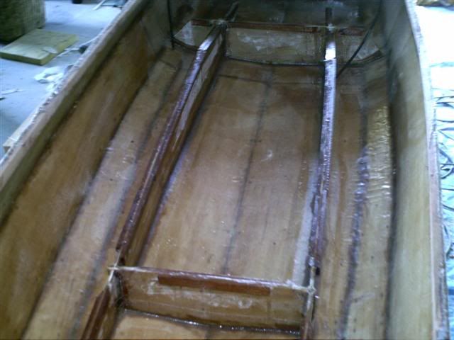
The measurement from the corner of the "L" shapes part of the long cockpit frames to the notches for the cross supports seems to be different than the measurment from the end of the stiffeners and the same notch. Especially on the the cockpit floor part of the stiffener (it's a little shorter). The total length from corner to corner on the "L" shaped part of the frame is just about 4'. I am just having trouble drawing without the reference points mapped out for me.
Do you suggest that I cut one and use it as a template for the other? Is the length important, or are the stiffeners just there for extra support? I wanted to draw everything before I started cutting, and am only having trouble with these two peices. I can get the measurements from the other drawing for the angle on top but there seems to be a curve on the bottom. I kind of need the reference points to draw the curve, The math is the geometry knowledge I need to plot it all out, I think I can do it but don't want to cut and be wrong.
Posted: Sat Jul 21, 2007 8:45 pm
by jem
I'm assuming you're talking about Sheet #4.
Drawing the stiffener on 4.2. After you cut that out, you'll use that as a pattern to make the other mirrored, horizontal copy, and then the vertical copies.
Posted: Sat Jul 21, 2007 9:24 pm
by jem
I sent you an additional QA file so you can check the first copy before cutting. That will become a regular part of the plans now.
I got that part
Posted: Sun Jul 22, 2007 5:01 am
by pogue3one
But the distance between the forward notch on the forward end of the cockpit frame and the forward cockpit wall support is different than the distance between the forward notch and the forward end of the stiffener. what is the distance between the forward edge of the notch and the forward end of the stiffener. On the plans it appears to be about half the distance. This makes me wonder if the aft end measurements are different even though they look pretty much the same. Or is it important at all?
Sorry so daft. I guess the plans aren't Marine proof.
Posted: Sun Jul 22, 2007 7:31 am
by hairymick
Mate,
I don't have my wade fish drawings handy but I am assuming you are talking about the little strips that glue along the tops of the cockpit supprt frames? The ones that the cockpit will eventually sit on?
If so, all you need is clearance so that they don't interfere with the cross supports and their stiffeners when assembling the frames.

Both sides need to be as identical as you can make them. I would mark one side, check it, then cut it and then is it to mark the opposite side support.
Hope I have helped a bit and not confused you more.
Are these the stiffeners you are talking about?
Newer version of the plans
Posted: Sun Jul 22, 2007 11:46 am
by pogue3one
The newest version of the plans has stiffeners that nearly mirror the frames themselves, that eliminate the need for the gluing of the strips. The two fore-and-aft stiffeners are cut shorter and have lightening holes.
I do appreciate the help. I think I know the answer. I just don't want to find out that I'm wrong AFTER I cut